Case Studies

Monitoring of a Self-Propelled Sprayer with Eurosens MWS

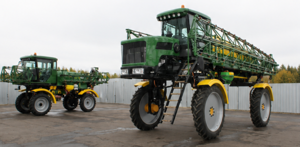
Object: Self-propelled sprayer BARS-3000 24m (mechanics) ground clearance 1.3m

Project: GPS/GLONASS monitoring and telemetry: control of the level of liquid fertilizers in the sprayer.

Note: this case describes a real agricultural monitoring project. Actual results depend on machine condition, field profile and operating practices.

Monitoring of a Self-Propelled Sprayer with Eurosens MWS

Liquid fertilizer level control with GPS/GLONASS telematics

Project object

Self-propelled sprayer BARS-3000, 24 m boom, mechanical version, 1.3 m clearance.

The sprayer is used for crop protection operations and for applying liquid mineral fertilizers
such as UAN and other liquid fertilizer solutions during the vegetation period.

24 m Working boom width
1.3 m Clearance
RS-485 Eurosens MWS interface


Challenge & Eurosens Solution

From route deviation risk to controlled fertilizer application

Initial risks

    1. Deviation from the assigned route.
    2. Uneven fertilizer application.

The customer needed a single reliable data flow for location, liquid fertilizer level and operational reporting.

Implemented solution

A GPS/GLONASS monitoring terminal was combined with the Eurosens MWS distance sensor installed for fertilizer tank level measurement. Tank calibration converts measured distance into liters.
Solution Architecture

How the monitoring system works

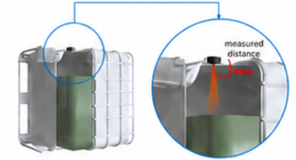
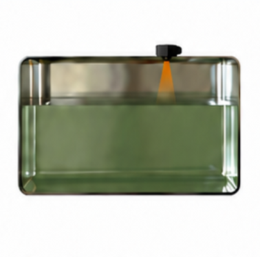
Eurosens MWS measures the distance to the liquid surface inside the tank.
The monitoring platform converts this distance into tank volume using a calibration table.

System components

GPS/GLONASS terminal track, mileage, geozones, stops.
Eurosens MWS radar distance to liquid surface.
RS‑485 Modbus RTU digital data transfer.
Monitoring platform reports, events, alerts.


MWS measures distance to the liquid surface
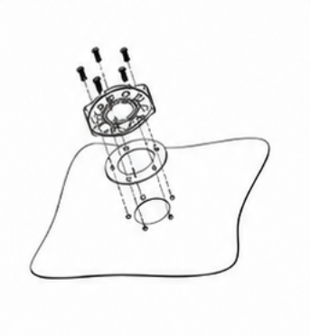
Bayonet mounting / tapping installation
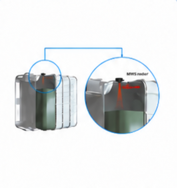
External mounting is possible for suitable plastic tanks
 

Implementation steps

  1. Install the GPS/GLONASS monitoring terminal on the sprayer.
  2. Install and connect Eurosens MWS to the sprayer tank via RS-485 / Modbus RTU.
  3. Calibrate the tank so measured distance is converted into fertilizer volume.
  4. Configure the object, controlled parameters, reports and notifications in the monitoring platform.
Parameter Value
Power 10–50 V
Interface RS‑485
Protocols Modbus, LLS
Protection IP67
Temperature range –40…+85°C

What the customer receives


Confirmed work route: track, working distance, geozones and stops.
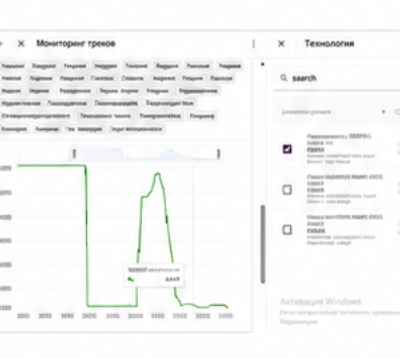
Visible fertilizer level dynamics in the sprayer tank during the shift.
Refills, drains and abnormal level drops available for dispatcher alerts.
Daily reports for dispatcher, mechanic and field‑area manager.
Better comparison of fertilizer consumption with treated area.
Example of level graph/report screen


Example daily report


The original case provides a sample report showing fertilizer consumption per day, treated area, working path and end-of-day residual volume.

Date Consumption, L/day Area, ha Working path, km Evening residual, L
10.04.2026 2,850 20.4 8.5 150
11.04.2026 2,890 18.6 7.8 110
12.04.2026 2,810 16.5 6.9 190

Estimated fertilizer savings

  • About 720 L over the 3‑day sample period
  • Around 240 L/day
  • Potential savings: up to 4,800 L per 20 working days
  • Savings sources:
    preventing over‑application
    route control
    timely detection of abnormal level drops


Operational value


For dispatcher

  • Real‑time route confirmation
  • Geofence control
  • Stop analysis
  • Alerts on sharp fertilizer level changes

For mechanic

  • Clear data on sensor status
  • Tank calibration
  • End‑of‑day residuals for service checks

For manager

  • Daily consumption reports
  • Comparison of input use, treated area and productivity by sprayer

Installation note

For metal tanks, MWS requires tapping/drilling. For tanks made from suitable dielectric materials, external non-drilling mounting can be considered after checking tank wall thickness and product properties.

Eurosens MWS photo gallery

Photos and diagrams used in this case

The following images show the Eurosens MWS sensor, installation principle and typical level‑measurement applications used to explain the sprayer tank monitoring project.

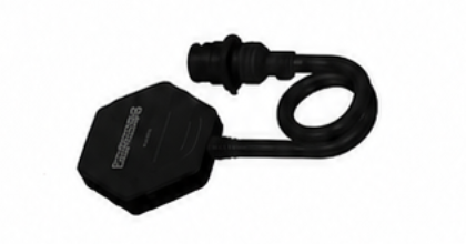
Eurosens MWS sensor
Tank level measurement principle
Example of external mounting on plastic tank

Radar distance measurement for bulk products
 

Eurosens MWS sensor

We use cookies and process personal data to improve the website. By continuing to use the site or by clicking the “Accept” button, you agree to the use of cookies in accordance with our Privacy Policy.